
These pictures were taken in December 1997 with an Olympus D-300L digital camera. We've been meaning to take better pictures using a tripod and a close-up lens where needed, but due to popular request we're posting the current pictures.
Click on the smaller image to display the full-size image. Important Note: The larger images have been known to crash older versions of some web browsers, in particular the 16-bit versions of Netscape.
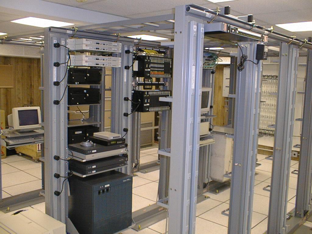
A view of the main POP area.

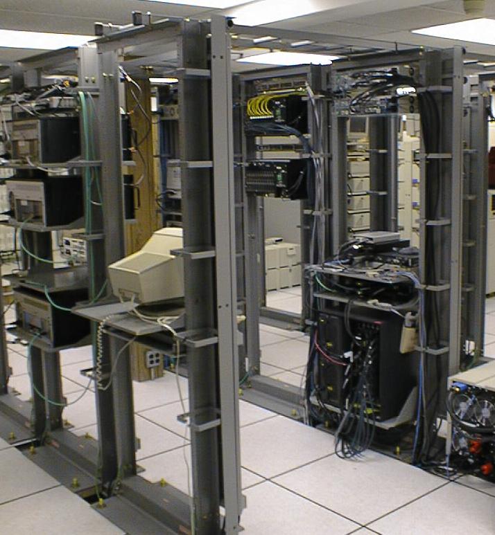
Another view of the main POP area. In the back right you can see one of the two air conditioners.
The main POP area from a different point of view.
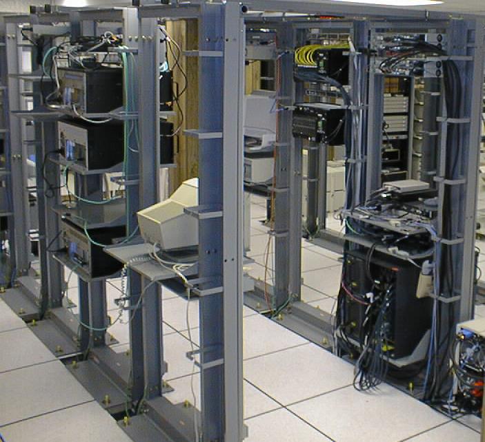
Another view of the main POP area.
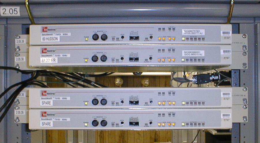
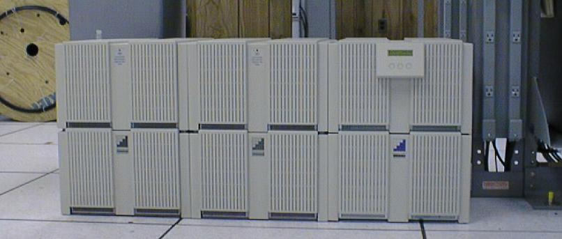
4 T3 CSU's (front view).
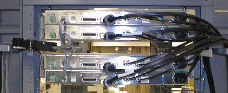
Rear view of the 4 T3 CSU's. Note the wiring of the control and alarm ports, as well as the individual ground connections.
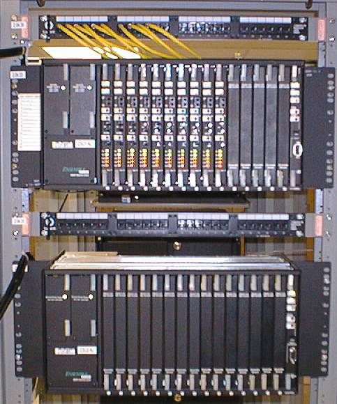
Two T1 CSU shelves, each holding 15 T1 CSU's. The rightmost card in each shelf is a management card that provides Ethernet access and SNMP monitoring for the 15 T1 CSU's. The yellow cables above are individual T1 patch cables. The strip they are plugged into is routed to a patch panel on the wall to the right.
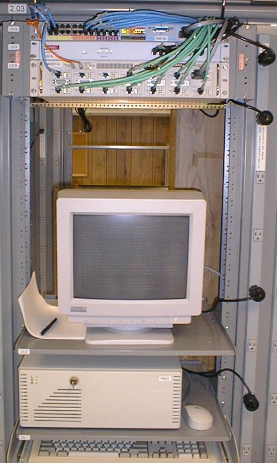
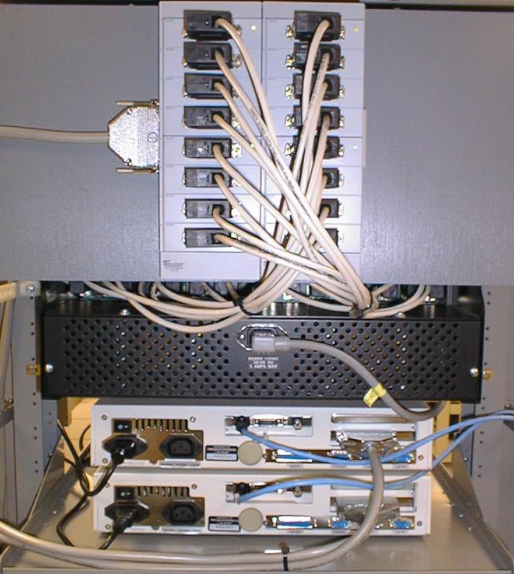
Our on-site maintenance PC (pingus.new-york.net, running BSD/OS). Above it is a 24-port 10Mbit Ethernet hub as well as a 100Mbit Ethernet hub and a 10/100Mbit Ethernet switch. This has since been replaced with two Cisco 10/00Mbit Ethernet switches. Note the color-coding of cables (blue for 10Mbit infrastructure ports, black for 100Mbit infrastructure ports, and green for colocation customers.
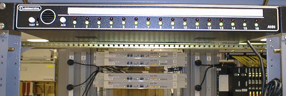
This is a central annunciator panel. It monitors the alarm contacts on our CSUs and other devices, and sounds a local alarm in the event of a problem. It also sends a SNMP trap to our central monitoring station. The white strip is labeled with the location of each monitored device. The red and green LED's show the status of each device. In the background you can see the T3 and T1 CSU's in the next row, as well as the separate A and B power strips, supplied by two independent UPS systems.
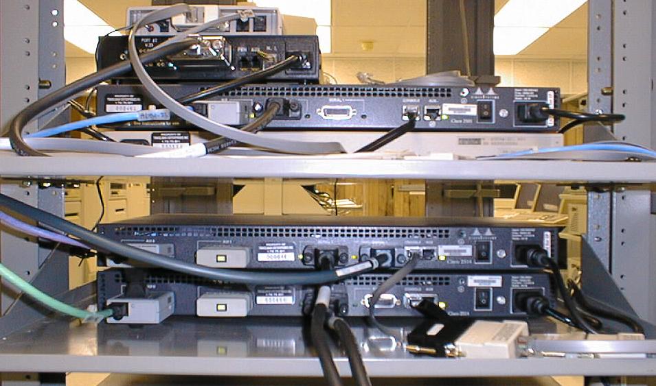
While our main routers are 7500-series routers, some applications require a smaller router. On the lower shelf we have 2 2500-series routers dedicated to colocation customers. On the upper shelf we have a terminal server and modem (bottom and top of the stack, respectively) for remote access and control of the console ports of the various devices in the POP. In the middle are a 2500-series router and a T1 CSU used for testing - we can reproduce customer configurations on these for troubleshooting purposes.
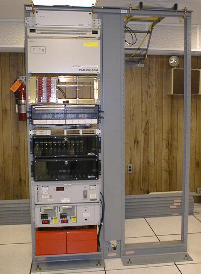
Our data circuits are delivered to the POP by Bell Atlantic. In the left rack is an OC-3 multiplexor delivering 28 T1's and 2 T3's. The top box is a fiber optic patch panel. Below it is the FLM150 multiplexor. Next are lightning protectors for the T1's (for some strange reason, Bell Atlantic puts protectors between the mux and the NIU's, despite the fact that it's all indoors). Below that are the T1 and T3 test jacks. The large black panels are spaces for 28 T1 NIU's (loopback/test units). Also, despite a number of vendors making higher-density units (that would fit in less than half the space), Bell Atlantic still uses these older, bulky units. In New York, Bell Atlantic uses the nicer ones. On the bottom of the rack, we have the battery backup for the multiplexor (the orange batteries and the gray chargers above them). This gives us nearly a day of run-time in the event of a power failure. Since this picture was taken, we have added an OC-12 multiplexor and battery plant in the right-hand rack.
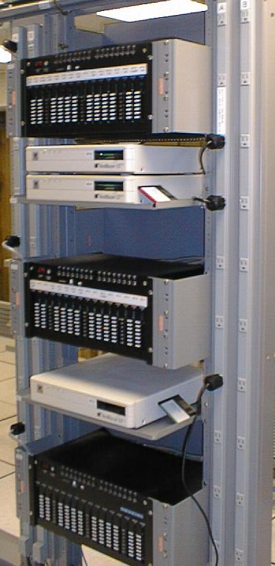
At the time we took these pictures, we were using Telebit NetBlazers and Microcom modems for our dialup users. They are quite reliable, just rather bulky by today's standards. We have installed a Cisco AS5300 which supports up to 92 calls in about 5" of rack space and are migrating users to it. However, we have some users with private line circuits and it's likely that we will still have at least one NetBlazer and modem shelf in the POP for some time to come. Here you can see 3 NetBlazers and 3 modem shelves.
The Netblazer uses Specialix intelligent multiplexors to provide 16 lines that run at 115200BPS. However, there is no convenient way to mount these devices (which we call "pods".) Here you can see that we've mounted a board behind the modem cage and attached the pods to it. The smaller white cables go behind the board to the modem cage. The large gray cable with the silver connector on the left attaches the pods to the controller card in the NetBlazer.
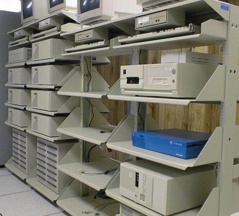
In addition to the main rack area of the POP, we have another section which contains server stands. Here you can see four of the stands. The two on the left contain some of the New York Net systems installed in the POP (the systems pictured are mail1, mail3, news, news2, news3, news4, ns1 and www) as well as colocated customer systems on the two right-hand stands.
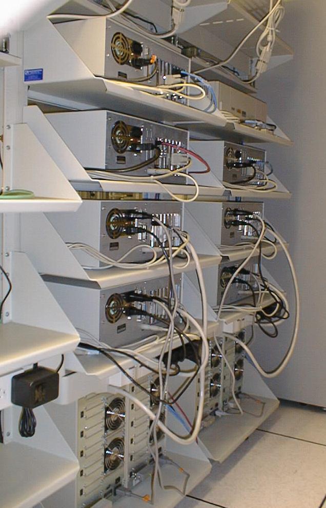
This is a view of the back of the two left-most stands (containing the New York Net systems). The fat cables are SCSI cables connecting the four news servers to their RAID arrays on the bottom of the stands. Since this picture was taken, we've added a 1GB solid state disk (SSD) to news to improve performance (news.new-york.net is currently [December 1998] the #144 news server on the Internet).
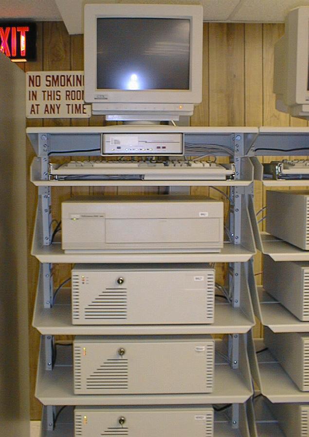
This is a straight-on view of the top of the left-most server stand. The systems shown here are mail1, mail3, news2 and news4. The small box below the monitor is an electronic keyboard/mouse/monitor switch that lets us access any of the 4 systems on the stand.

This is a view of two of the RAID arrays used for news. Each of the drive trays is hot-swappable in the event of a disk failure. At the very bottom of the picture you can see 2 bolts covered with yellow protective covers. These bolt the server stand to the concrete sub-floor.
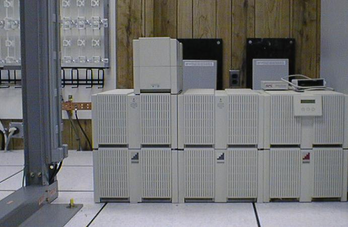
This is one of 3 APC Matrix 5000 uninterruptable power supplies installed in the POP. This one supplies the "A" outlet strips on the racks. An identical unit provides power for the "B" outlets. Since most of our equipment has dual AC power supples, we can perform UPS maintenance without disrupting service. Each of these systems is configured for approximately 6 hours of run-time.
This is the Matrix 5000 UPS that provides power for the server stands. It is also configured for 6 hours of run-time. To the left of the UPS you can see part of one of the interconnect frames mounted on the wall. On the bottom of the frame you can see the master ground bar for the POP - each rack is bonded to the master ground with two wires, and each device is grounded to the rack it's mounted in.
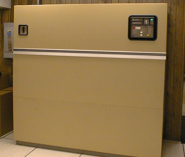
This is one of two Liebert air conditioners that provide climate control for the POP. Each unit is capable of maintaining the environment by itself - two units are used for redundancy.