
These are pictures of various other provider's equipment. The intent is not to poke fun at their equipment or wiring, but to provide an honest comparison of various installation styles. In some case I've made various comments about the pictures, which represent only my personal opinion. Furthermore, in almost all of these cases I have not discussed the configurations with the providers, so my comments may well be based on incomplete information or incorrect assumptions. As always, if you are curious as to how your provider's equipment is configured, ask them for a tour of their facilities.
If you are a provider and want to display images of your equipment and wiring here, send me email and I'll arrange it.
Click on the smaller image to display the full-size image. Important Note: The larger images have been known to crash older versions of some web browsers, in particular the 16-bit versions of Netscape.

This probably started out neat, but since cables were not made to length and weren't bundled out of the way, it's become difficult to access the cards in the 7513 router at the bottom of the cabinet. Also, later unsupervised telco circuit installations have caused jacks to sprout all over the cabinet - some are stuck on the left-side rail and one is even stuck on the blower at the top of the 7513.
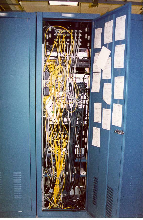
The neighboring cabinet to the one in the previous photo. Pretty much the same comments apply. This whole cabinet could probably be replaced with a pair of channelized T3 cards. The white slips of paper on the door are telco circuit delivery notices.
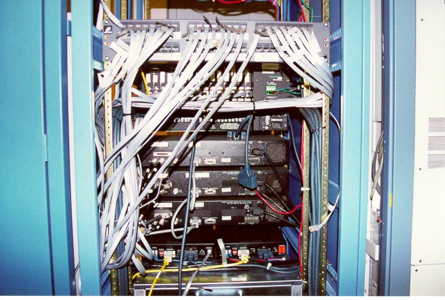
This apparently started out neat. However, as changes were made, it appears that old, no-longer-used cabling was left in place as you can see from the various dangling ends. Compare this with our cabinet, which uses the exact same Digital Link CSU shelves.
The bottom of the cabinet shown in the above picture. The sheer density of the serial cables (there are 7 FSIP cards, for a total of 56 T1's) mean that swapping a card (if it fails) will be very problematic. Also, while each cable is tagged with the customer name, it doesn't have the slot/port info, so additional note-taking would be required before disconnecting the cables. Likewise, compare the serial cabling with our cabinet.
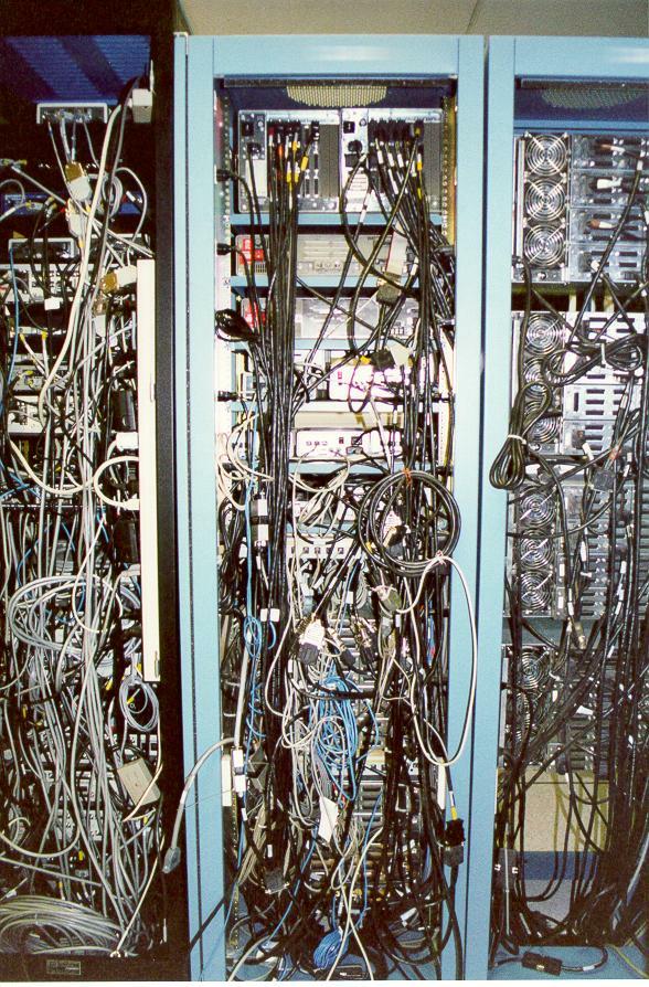
This picture pretty much speaks for itself. These cabinets have older, low-port-density equipment and way too many interconnect cables. Much of the equipment has been disconnected (note the large number of empty connectors on the equipment in the right-hand rack) but not removed. None of the cables are made to length, and the excess is either rolled up or stuffed under the floor.
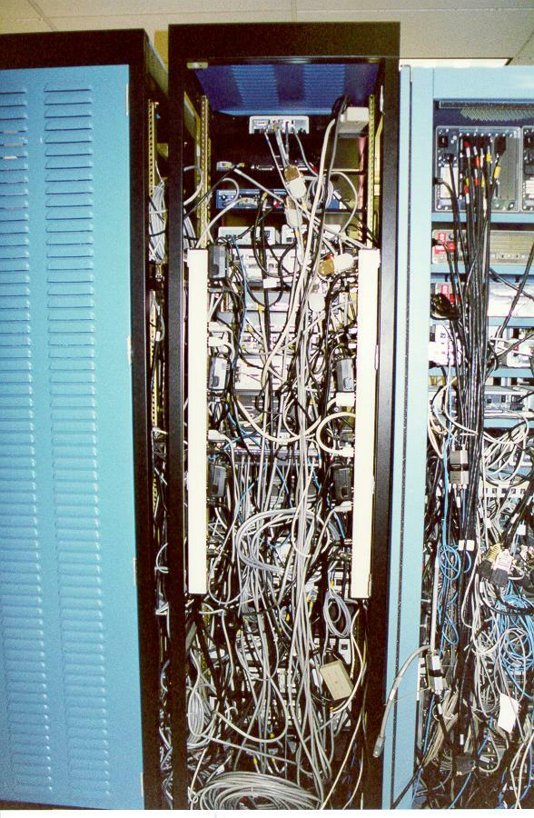
Another view of the same equipment from the above picture.
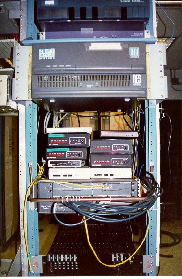
This doesn't look too bad...

...until you go around the back. It looks like this equipment just expanded slowly, a piece at a time. Installing a rack-mount CSU (or the Cisco CSU-on-a-card modules) and trimming the cables to length would probably clean this up nicely.

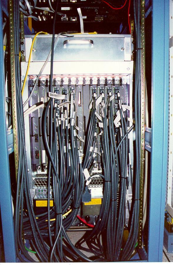
This is what happens when you let the phone company install cables for you. The whole mass of cables are individual T1 cables connected to various routers. Some of them are just dangling, probably because nobody knows where the other ends are. The rest actually connect to some equipment...

...and this is one of the newer routers. On the right are the Cisco CSU-on-a-card modules, which proves that even if you use the newer modules, you still need a structured cabling system or you wind up with a mess.