
These pictures were taken in January 1999 with an Olympus D-300L digital camera, just before the cabinet was shipped from our assembly area to the POP. The Olympus digital camera's autofocus had a terrible time with this cabinet due to the varying depths of the equipment mounted in it.
Click on the smaller image to display the full-size image. Important Note: The larger images have been known to crash older versions of some web browsers, in particular the 16-bit versions of Netscape.

A view of the top section of the cabinet, from the front. At the top, you can see the cooling fan and environmental sensor. Below them are the CSU shelf with 12 T1 CSU's and the Ethernet/SNMP management processor. Immediately below the CSU shelf is a fan tray for cooling the CSU's (since this is an unattended POP in a colocation space, we don't have complete climate control). Next is a Cisco 4700M router.
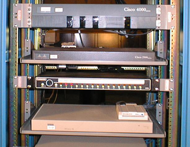
Moving down the front, we see the same 4700M router as in the previous picture. Below that is a Cisco 2514 used for local Ethernets at the POP. Next is an alarm annunciator panel which has a local alarm buzzer, as well as reporting alarm events to our main SNMP monitoring station. The two red alarms are for the front and rear doors, since they're open. Below the annunciator are a modem and a terminal server, used for remote maintenance (it connects to the console ports of every device in the cabinet).
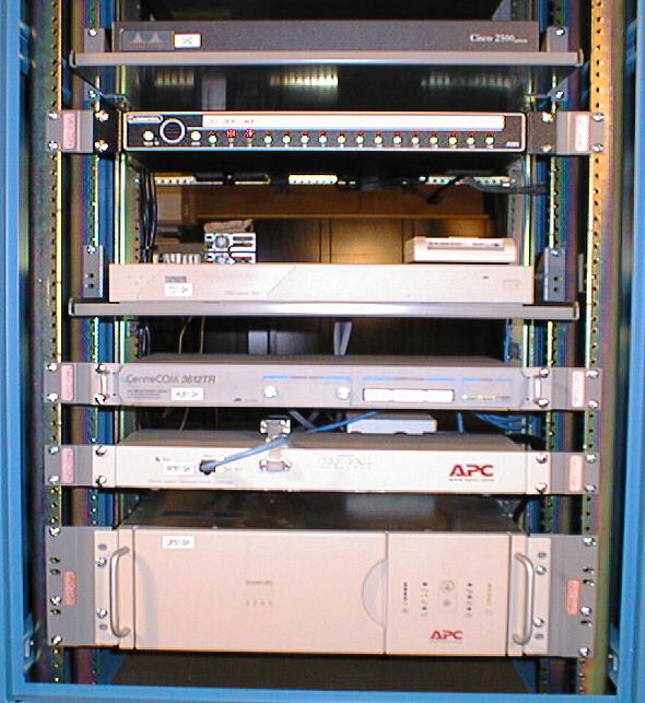
In the bottom view of the front, we see the 2514, annunciator, modem, and terminal server from the above picture. Below that is the Ethernet hub for the local Ethernet in the cabinet. Next is a remote power switch (we can individually power cycle each device in the cabinet). At the bottom is an APC SU2200RM UPS.
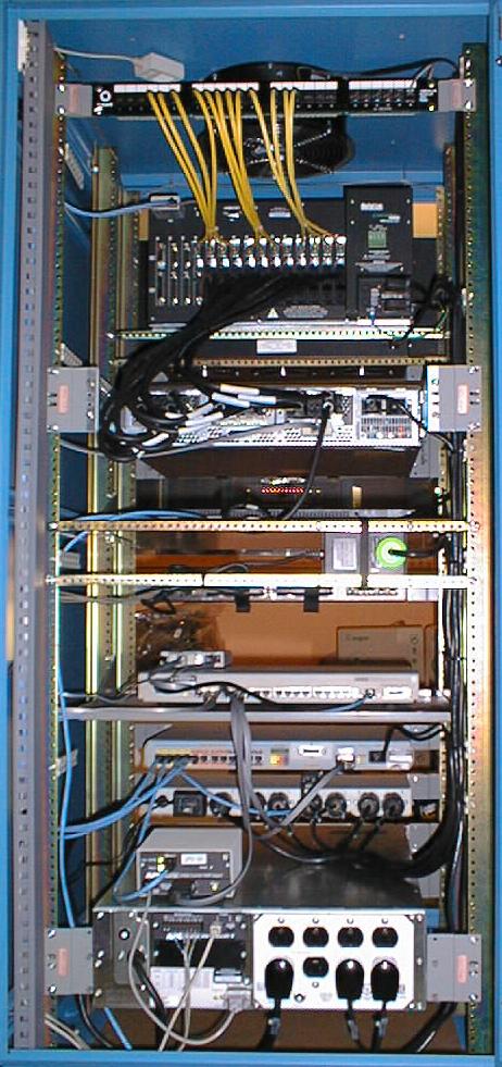
This is the view of the rear of the cabinet. In addition to the items listed in the front views, you can see the "zip strip" on the left side of the cabinet, which we use to organize the internal cables. You can also see the T1 patch panel and its yellow T1 cables. Halfway down the picture is the "wall wart" transformer for the annunciator, mounted on a pair of lashing bars. On top of the UPS you can see the SNMP adapter for the cabinet (the slot in the UPS is taken by the environmental monitoring controller).