
These pictures were taken in February 1995 with a Polaroid camera. These pictures were taken shortly after we moved our POP from the 2nd floor of 60 Hudson to the 15th floor. We started with the 3 cabinets shown in these photos, but we now have 7 cabinets as well as some additional wall-mounted enclosures.
These pictures do not represent the current equipment at our 60 Hudson POP - they are here to show you what our first POP looked like, and to allow you to compare these pictures with our current 60 Hudson POP.
Click on the smaller image to display the full-size image. Important Note: The larger images have been known to crash older versions of some web browsers, in particular the 16-bit versions of Netscape.
Also, each of the smaller images has a button to the right, which you can click to see a similar view today (May 1999).
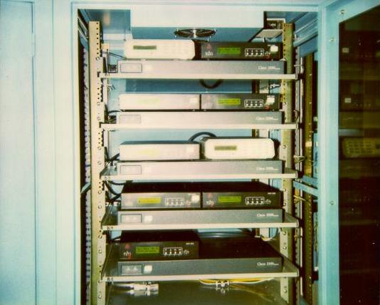

Our first stack of routers, 5 Cisco 2501's. At the time these pictures were taken, we had a T1 to Sprint (for Internet transit), a T1 to NYNEX Frame Relay, a T1 to the Jersey City POP, a T1 to the Queens POP, and a variety of point-to-point connections to customers. Of note is the Adtran 64K CSU on the top shelf - it connected to a customer in Israel (we had already signed up our first international customer by this point). On the bottom (empty) shelf, you can see the pre-wired T1, Ethernet, and console cables used for expansion. The rest of the cabinet was similarly pre-wired.
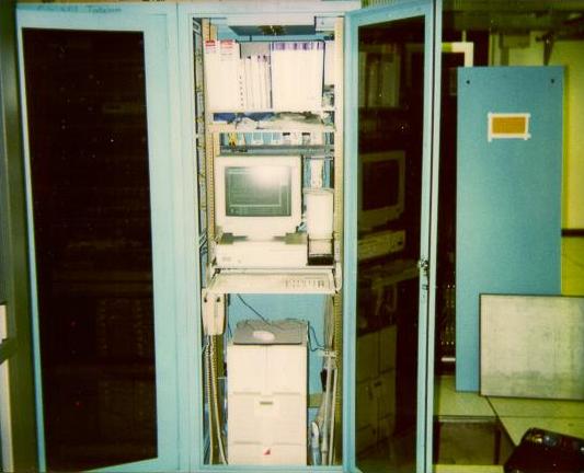
A view of our "support area" in the rightmost cabinet. As originally planned, we used the left cabinet for modems and access servers, the middle cabinet for routers and CSU's, and the right cabinet for a UPS and support functions.
At the top of the cabinet is a documentation shelf. Of particular interest are the blue-topped Cisco manual set. At the time this picture was taken, a complete set of Cisco manuals was only about 10" thick. Below that we have a shelf with a PC and monitor. Next is a keyboard shelf and rack-mounted telephone. On the bottom is an APC Matrix 3000 UPS with 2 SmartCell batteries. The top of the UPS is being used as a mouse pad. To the right, behind the floor tile, you can see the cabinet side panel (it was removed while we were working in the cabinet) with the infamous "This space reserved for Tinkelman expansion" sign taped to the panel.
Two Telebit NetBlazer ST's and their associated Microcom 28.8 modem shelves. We used this equipment to provide a small amount of SLIP/PPP dialup service to our leased-circuit customers.
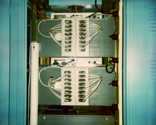
This is a view of the back of the NetBlazer/Microcom equipment from the previous photograph. Unfortunately, NetBlazers use large, unwieldy "pods" for their serial ports, and the Microcom modem shelves have their serial connectors in a rather inconvenient place. Our solution was these plywood backboards, on which we mounted the NetBlazer pods and ran cables to the Microcom serial connectors. To the left, you can see a fluorescent trouble light, which is just stored there until it's needed.
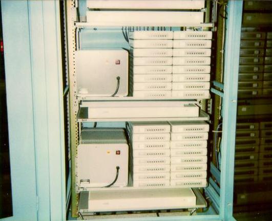
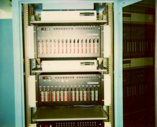
Two shelves worth of DECserver terminal servers, 14.4 modems, and custom-built "power pods". These were used to provide "a remote POP" for some of our customers - we would configure the terminal servers to auto-connect callers to our customers' systems, giving our New Jersey customers New York City dialup numbers without their having to have their own space in New York.
At the time we built this POP, 28.8 modems were still quite new (the 28.8 standard was quite a ways off) and many customers were requesting 14.4 modems as there were some compatibility problems when older modems called 28.8 modems. Rackmount modems were much more expensive than standalone units, and we did not want to invest heavily in 14.4 rackmount modems. So we used standalone AT&T Dataport modems. However, rather than having a stack of 32 transformers, we custom built the power supplies you see to the left of the modems. These supplies powered 16 modems each, and were quite successful.
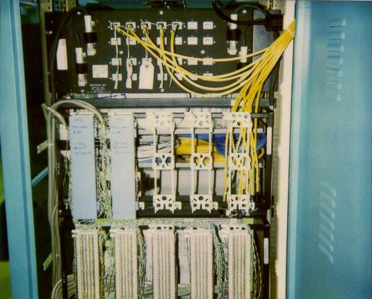
This picture shows the delivery of the MFS circuits. The large ugly panel on the top is an "IPL panel", which was MFS' preferred way of deliverting T1's. Later on, we moved T1 delivery to a wall-mounted cabinet using Krone blocks in order to free up space and make reconfigurations easier. The yellow cables near the IPL panel are T1 circuits, connected to the CSU's in the first photo. The dangling yellow cables were for expansion (we pre-wired the middle cabinet so we could add routers and CSU's without needing to run any additional cables). Below the IPL panel are two blue-covered 66 blocks where MFS delivered analog phone lines for our modems. Below that are 66 blocks with clear covers, which connect cables running to the other cabinets. This way we could reconfigure phone lines by simply changing the jumpers between the 66 blocks, rather than needing to run new cables between the cabinets. Like the T1 cables, many of these blocks were connected to pre-wired empty spaces in the first cabinet.